| Up: |
|
Components of the BRDF |
| Previous: |
|
Specular component |
| Next: |
|
Uniform diffuse component |
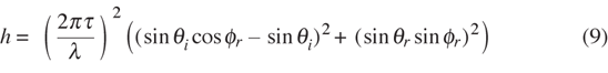
The directional diffuse component spreads reflected light out to the entire hemisphere above a reflecting surface. The component has a very strongly-directional, nonuniform character. It is responsible for highlights of light sources and blurry reflection images on a rough surface. It arises from diffraction and scattering by the surface roughness. The reflected radiance can be expressed as a product:
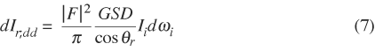
Note that the incident solid angle dωi appears in Equation (7). In the interactive figures that have a dωi the coefficient of dωi is approximated using a midpoint rule, and dωi is evaluated assuming a circular cross-section. The values of solid angle shown for “dOmega” on the control panels have been multiplied by a scale factor of ten. The actual solid angles are one-tenth of the values shown. The maximum slider value of unity corresponds to a maximum incident cone angle of 20.4°. This represents an incident solid angle of 0.1 steradians, or 1/20π = 1.6% of the incident hemisphere.
The illustration below demonstrates how the geometric factor G varies with incidence angle θi. The incidence direction is shown with the red line. The semicircle is the unit hemisphere. The function G arises from geometric projections of the incident and reflected directions onto the surface and is given in [HE91].
Figure 11: Interactive display of geometric factor G
The distribution function D is given by the following infinite summation:
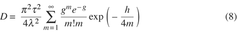
The illustration below shows how the distribution function D varies with θi, σ, τ, and λ. The semicircle is the unit hemisphere. The incident direction is shown with the red line on the left; the dashed line to the right indicates the specular direction with respect to the mean plane of the surface.
Figure 12: Interactive display of the distribution function D
Finally, let's see how the entire directional diffuse component
dIr,dd
varies with the parameters
θi, σ, τ, λ,
and material. This is shown in Figure 13, where the incident
light cone is on the left and the specular-ray direction for the mean
surface is indicated on the right (dashed line). The dashed
semicircle is added for reference, and corresponds to Lambertian,
ideal-diffuse, 100% reflection of the incident beam. For such a
reference reflector, the reflected radiance is
![]() where dEr is the reflected energy flux. The π-factor
arises when converting energy flux to radiance for a Lambertian
surface. For a 100% reflector,
dEr = dEi,
with dEi given by Equation (2). Thus,
where dEr is the reflected energy flux. The π-factor
arises when converting energy flux to radiance for a Lambertian
surface. For a 100% reflector,
dEr = dEi,
with dEi given by Equation (2). Thus,
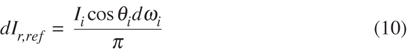
and we see that the radius of the reference hemisphere varies with θi and dωi.
Figure 13: Interactive display of entire directional diffuse term
| Up: |
|
Components of the BRDF |
| Previous: |
|
Specular component |
| Next: |
|
Uniform diffuse component |
| Converted to HTML by Stephen H. Westin <swestin@earthlink.net> Last modified: Mon Sep 5 23:19:34 EDT 2011 | This document is not valid HTML. Look here to learn why. |